OpenGL data pipeline: From CPU to GPU Memory
Introduction
When working with OpenGL, one of the most fundamental — yet often confusing — questions is:
“When I draw a triangle, where does my data actually go?”
Understanding this journey clarifies how data moves from the CPU to the GPU, and why certain API calls matter more than others. This article bridges that gap — walking through vertex data, buffer objects, draw calls, and shader execution — to reveal how OpenGL manages memory and transforms your data into rendered pixels.
1. The Foundation: Vertex Data and Buffer Objects
1.1 What is a VBO (Vertex Buffer Object)
A VBO stores vertex attribute data — such as positions, normals, or texture coordinates — directly in GPU memory.
- Created and filled using:
const float combinedVBO[] = { ... }; GLuint combinedBuffer; glGenBuffers(1, &combinedBuffer); glBindBuffer(GL_ARRAY_BUFFER, combinedBuffer); glBufferData(GL_ARRAY_BUFFER, array_length(combinedVBO) * sizeof(float), combinedVBO,GL_STATIC_DRAW); - The data itself is just raw bytes; meaning is only given later when attributes are defined via layout specifications.
1.2 What is an EBO (Element Buffer Object)
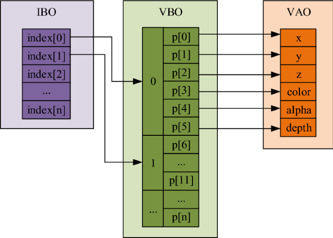
An EBO (or Index Buffer) stores integer indices that reference vertices in a VBO.
- Enables vertex reuse, avoiding duplication and improving memory efficiency.
- Bound and used like this:
// Bind the VAO first, this is important! So that OpenGL knows which VAO the EBO belongs to. glBindVertexArray(vertexArrayObject3); unsigned int indices[] = { 0, 1, 2, // first triangle (top-left) 2, 1, 3 // second triangle (bottom-right) }; GLuint ebo; glGenBuffers(1, &ebo); glBindBuffer(GL_ELEMENT_ARRAY_BUFFER, ebo); glBufferData(GL_ELEMENT_ARRAY_BUFFER, sizeof(indices), indices, GL_STATIC_DRAW); - The active VAO remembers which EBO is currently bound for indexed drawing.
1.3 What is a VAO (Vertex Array Object)
A VAO is a container that describes how vertex data is read.
- It remembers:
- Which VBOs provide which attributes.
- How each attribute is laid out (stride, offset, and type).
- Which EBO is used for indexed rendering.
You can think of a VAO as an “input layout blueprint” for your vertex shader.
And you can set up VBOs and VAO in different ways, depending on your needs. In the following section, I will show two common patterns.
- Use one huge VBO with interleaved attributes.
const float combinedVBO[] = {
  0.0f,  0.0f,  1.0f,  // v0 pos
  0.0f,  1.0f,         // v0 uv
  -0.5f, -0.8f, 1.0f,  // v1 pos
  0.0f,  0.0f,         // v1 uv
  0.5f,  -0.5f, 1.0f,  // v2 pos
  1.0f,  0.0f,         // v2 uv
};// All attributes packed together
glBindBuffer(GL_ARRAY_BUFFER, combinedBuffer);
glBindVertexArray(vertexArrayObject3);
// So here we need stride and offset to tell OpenGL how to read the data
glVertexAttribPointer(0, 3, GL_FLOAT, false, 5 * sizeof(float), 0); // pos
glVertexAttribPointer(2, 2, GL_FLOAT, false, 5 * sizeof(float), (void*)(3 * sizeof(float))); // uv
glEnableVertexAttribArray(0);
glEnableVertexAttribArray(2);
And the code above shows how to set up the attribute pointers for interleaved data.
- Use separate VBOs for each attribute.
const float seperatedVBOPos[] = {
  0.0f,  0.8f,  1.3f,  // v0 pos
  -0.5f, -0.8f, 0.9f,  // v1 pos
  0.5f,  -0.5f, 0.9f,  // v2 pos
};
const float seperatedVBOUV[] = {
  0.5f,  1.0f,         // v0 uv
  0.0f,  0.0f,         // v1 uv
  1.0f,  0.0f,         // v2 uv
};
// Set up VAO and Bind VAO first
glGenVertexArrays(1, &vertexArrayObject);
glBindVertexArray(vertexArrayObject);
// Bind target VBO before setting attribute pointers!!
glBindBuffer(GL_ARRAY_BUFFER, seperatedPosBuffer);
// Because we have separate VBOs, no need for stride and offset
glVertexAttribPointer(0, 3, GL_FLOAT, false, 0, 0); // pos
// Bind target VBO before setting attribute pointers!!
glBindBuffer(GL_ARRAY_BUFFER, seperatedUVBuffer);
glVertexAttribPointer(2, 2, GL_FLOAT, false, 0, 0); // uv
glEnableVertexAttribArray(0);
glEnableVertexAttribArray(2);
So now we can understand that how VAO points to different VBOs and how the data is laid out in those buffers. The key here is the set up of attribute pointers by glVertexAttribPointer( index, size, type, normalized, stride, offset).
1.4 Setting Up Vertex Input — APIs and Layout Patterns
Key APIs:
-
glGenBuffersvoid glGenBuffers(GLsizei n, GLuint* buffers);Purpose:
Generates one or more buffer object names (handles). Think of these as IDs that represent memory slots you can later fill and bind.Parameters:
n– Number of buffer names to generate. Usually1.buffers– Pointer to an array of unsigned integers that will store the generated buffer names.
Usage Tips:
- Use
glGenBuffers(1, &vbo)to create a single buffer handle. - This call does not allocate GPU memory yet — it only reserves an ID.
- You can generate multiple buffers at once for organization (e.g., one for vertex positions, another for colors).
-
glBindBuffervoid glBindBuffer(GLenum target, GLuint buffer);Purpose:
Binds the buffer name (handle) to a specific target — such as a vertex buffer or element buffer.
Once bound, all subsequent buffer operations (likeglBufferData) affect that target.Parameters:
target– Specifies the purpose of the buffer:GL_ARRAY_BUFFER: For vertex attribute data (positions, normals, UVs, etc.)GL_ELEMENT_ARRAY_BUFFER: For index (EBO) data used byglDrawElements
buffer– The buffer handle to bind, previously generated withglGenBuffers.
Usage Tips:
- Always bind before uploading data!!
- You can bind
0to unbind a buffer and return to default state. - The currently bound buffer is tracked per target; switching targets or binding another buffer changes the global OpenGL state.
-
glBufferDatavoid glBufferData(GLenum target, GLsizeiptr size, const void* data, GLenum usage);Purpose:
Allocates GPU memory for the currently bound buffer and optionally uploads data to it.Parameters:
target– Must match the target used inglBindBuffer(GL_ARRAY_BUFFER,GL_ELEMENT_ARRAY_BUFFER, etc.)size– The total size in bytes of the data to store.data– Pointer to your CPU-side data array (e.g., vertex positions).usage– A performance hint for the driver:GL_STATIC_DRAW: Data rarely changes (best for static meshes).GL_DYNAMIC_DRAW: Data changes occasionally (e.g., per frame).GL_STREAM_DRAW: Data changes every frame or every draw (e.g., particle systems).
Usage Tips:
- Always call this after binding the buffer.
- Now the buffer really exists in GPU memory!
- To update part of a buffer without reallocating, use
glBufferSubData.
2. Drawing: How Vertex Data Becomes Geometry
2.1 How glDrawArrays Works
- Fetches vertices sequentially from the bound VBOs according to the VAO layout. Even if an EBO is bound, it is ignored.
- Parameters:
(mode, first, count), by which it readscountvertices starting fromfirst. And ‘mode’ defines the type of primitive to render (e.g., triangles, lines). for example, drawing a triangle with 3 vertices:glDrawArrays(GL_TRIANGLES, 0, 3); - The vertex shader executes once per vertex; groups of vertices form primitives like triangles or lines.
2.2 How glDrawElements Works (Using EBO)
- Instead of sequentially reading vertices, uses indices stored in the EBO. And this EBO must be bound to the VAO before the draw call.
- Parameters:
(mode, count, type, indices), so before calling this function, you need to bind the current VAO which has the EBO bound. for example, drawing a rectangle using 4 vertices and 6 indices:glBindVertexArray(vertexArrayObject3); // VAO with EBO bound glDrawElements(GL_TRIANGLES, 6, GL_UNSIGNED_INT, 0); - Shared vertices are fetched only once, improving memory efficiency and performance.
2.3 Relationship Between VAO, VBO, and EBO
- VAO: Stores the layout and references to buffers.
- VBO: Holds the vertex data itself.
- EBO: Optionally provides indices for indexed rendering.
| Draw Call | Data Source | Uses EBO? |
|---|---|---|
glDrawArrays |
Sequential vertex order | ❌ No |
glDrawElements |
Indexed vertex order | ✅ Yes |
Both use the same VAO, but only glDrawElements references the EBO during draw calls.
3. Shaders: From Source Code to GPU Execution
3.1 The Shader Creation Pipeline
On the CPU side, shader code is plain text written in GLSL.
The creation process looks like this:
GLuint vs = glCreateShader(GL_VERTEX_SHADER);
glShaderSource(vs, 1, &vertexShaderSource, NULL);
glCompileShader(vs);

GLuint fs = glCreateShader(GL_FRAGMENT_SHADER);
glShaderSource(fs, 1, &fragmentShaderSource, NULL);
glCompileShader(fs);

GLuint program = glCreateProgram();
glAttachShader(program, vs);
glAttachShader(program, fs);
glLinkProgram(program);
Once linked, the program resides in GPU memory as compiled machine code.
From this point on, it’s ready for use during rendering.
3.2 Attribute, Varying, and Uniform Linking
layout(location = n)in the vertex shader corresponds toglVertexAttribPointer(n, …)on the CPU.- Variables shared between vertex and fragment shaders (varyings) must match names and types.
- Uniforms are constants per draw call — e.g., transformation matrices or material parameters.
4. Textures and GPU Resources: A Unified Memory Model
4.1 Textures as GPU Resources
- The CPU decodes images into raw pixels.
- OpenGL uploads them using:
glGenTextures(1, &tex);
glBindTexture(GL_TEXTURE_2D, tex);
// Generate texture data on GPU
glTexImage2D(GL_TEXTURE_2D, 0, GL_RGBA, width, height, 0,
             GL_RGBA, GL_UNSIGNED_BYTE, imageData);
free(imageData); // Free CPU memory after upload
- After uploading, texture data resides entirely in GPU memory.
4.2 Unified Resource Lifecycle
| Phase | API Example | Description |
|---|---|---|
| Create | glGen* |
CPU handle only — no GPU allocation yet |
| Bind | glBind* |
Changes driver state, tells GPU which object to operate on |
| Upload | glBufferData, glTexImage2D |
Allocates and fills GPU memory |
| Delete | glDelete* |
Frees the GPU resource |
This pattern applies universally across buffers, textures, and shaders.
5. The Big Picture: The Journey of a Vertex
At CPU side, you prepare your data each frame, rendering typically follows this sequence:
cpp
glClear(GL_COLOR_BUFFER_BIT | GL_DEPTH_BUFFER_BIT);

for (Shader& shader : shaders) {
    glUseProgram(shader.id);
    shader.bindGlobalUniforms();  // camera, lighting, etc.

    for (Renderable& obj : shader.objects) {
        glBindVertexArray(obj.vao); // this is 'mesh' from game engine perspective
        obj.bindMaterialUniforms(); // this is 'material' from game engine perspective
        glDrawElements(GL_TRIANGLES, obj.indexCount, GL_UNSIGNED_INT, 0);
    }
}
And then on the GPU side, here’s what happens under the hood:
- CPU creates vertex arrays, textures, and shader programs.
- Data is uploaded to GPU memory via OpenGL API calls.
- VAO defines how to interpret that data and links to an optional EBO.
- A draw call triggers vertex fetching and shader execution.
- The vertex shader transforms data; the fragment shader computes color.
- The GPU rasterizer converts geometry to pixels and writes them to the framebuffer.
key Takeaway
-
OpenGL operates as a state machine managing resources between CPU and GPU, so when you bind a VAO, VBO, EBO, or texture, you’re changing the current state.
-
VAO + Shader define how data flows; VBO/EBO/Textures define where data lives.
References
☕ Happy learning journey~ 🛠️